
So the screen from here is working in Kodi now (LCD datasheet / pinout), but it draws a lot of power when the backlight is on (~200mA extra). We want to turn at least the backlight off, leaving the touchscreen active so we can interact and wake it up again. Buuut the LCD has no backlight control which is a pity (would have cost close to nothing). Good thing is: We can easily add it.
UPDATE: This only needs a wire an NO software tinkering, but for the 5″ display you have to take it apart, because the IC is on the back side of the PCB. But this is the most convenient solution! Thanks Antje.
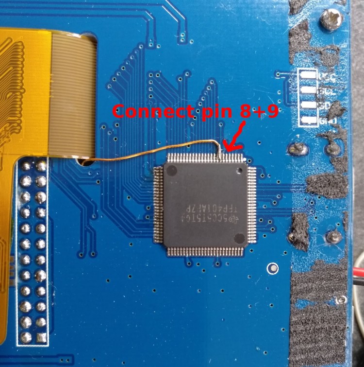
You’ll need a thin wire. Enamel wire works well here. The general idea is the same as in Antjes tutorial. Carefully seperate the screen from the PCB, solder a wire to pin 8+9 of the TFP401 and thread it through to the other side of the PCB.
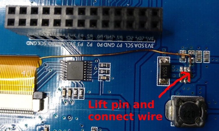
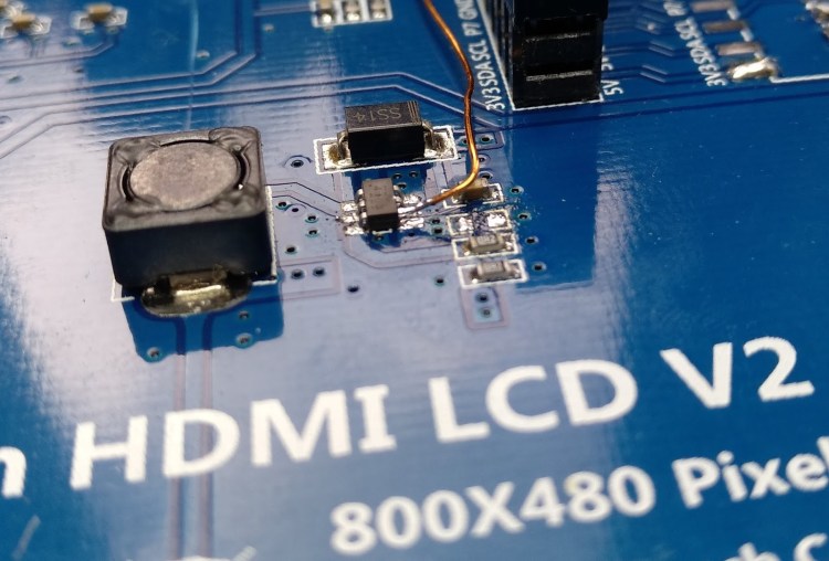
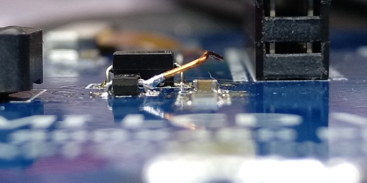
Now the problem for the 5″ screen is that pin 4 (ENable) of the PT4103 chip controlling backlight power is directly connected to 5V through some vias on the PCB. There’s no good way to cut that connection, so I used a soldering iron with a thin tip and gently lifted pin 4 of the PT4013 up, so it does not touch the PCB anymore. Then solder the wire from the TFP401 to it. That’s it.
Turning the screen on/off in Kodi
For the following instructions, use the home directory of the user you want to run Kodi from. If you make Kodi autostart by editing /etc/default/kodi, this is the user “kodi” (used here), else it is probably the user “pi”.
Now to integrate support for the backlight into Kodi, we need to run those commands when the Kodi screensaver starts or ends. For that we need a service addon called “service.xbmc.callbacks“. Download the script from the releases section and unzip it into /home/kodi/.kodi/addons. Now start Kodi and add those two lines in the addon configuration:
For screensaver starts:
vcgencmd display_power 0For screensaver stops:
vcgencmd display_power 1Your backlight should now turn off / on with the screen saver.

would that allow the backlight to be dimmed?If i would send gpio -g mode pwm gpio -g pwm 18 xwhere X = 512
LikeLike
Yes. It would. Note that 1023 does not seem to give me full brightness, only using the input/tristate mode does. If you find out how that can be improved, let me know…
LikeLike
Hi shouldnt you use a p-channel mosfet? currently your drain is directly connected to 5v. currently your load is on source and should be on drain
LikeLike
Oh, yes! You're totally right! Thanks. I corrected the picture and text…
LikeLike
Hello – I have a question or two, that I was hoping you could answer. But first, I want to apologize in advance if they doltish in any way, as I just started playing around with circuits a few weeks ago. Do you think an IRLZ44N transistor would work? Only reason I ask, is I have a bunch laying around and won't have to wait for them. I have no idea how to read these datasheets (http://www.infineon.com/dgdl/irlz44npbf.pdf?fileId=5546d462533600a40153567217c32725)Second, are you supplying power directly to the screen then to the pi? If so, this should still work if I use the usb port on my rpi2, correct?Lastly, what is that attached to your breadboard and what is it used for? Thank you very much. ap
LikeLike
The IRLZ44N is overkill, but should work. Power supply via USB should work too.The Thing on the Prototype Board is a Variable resistor, but a Fixed Value of 4.7k should be Just fine.
LikeLike
Thank you very much. Most helpful.
LikeLike
Hi, I have a few TIP122 as well as a few BC547and BC557 transistors and an assortment of RU3C 1.5A/1000V, RU4A, 6A10 6A/1000V, RU4D, 10A10 10A/1000V, 1N4007 1A/1200V, 1N4004 1A/400V, 1N4002 1A/100V, 1N4001 1A/50V lying around. I plan on making a similar hack to a 7\” Waveshare TFT LCD that uses the same PT4103 White LED Step-Up Converter to your screen, but I also plan to add a rotary pot to control the PWM via an MCP3008 ADC.Do you think I can substitute the MOSFET and your 1N4148 diode with a combination of what I have to make a similar circuit to yours? Which combination would you suggest? Thank you in advance!
LikeLike
For switching the backlight use a(ny) logic-level FET. You can try with an NPN-Transistor, but that might not work or require more circuitry. For the diode any general purpose diode should work.
LikeLike
There seems to be an another solution:http://capnbry.net/blog/?p=210
LikeLike
Hi, sollution with KodiCallback addon has weird behavior. If you touch the screen for deactivation screensaver, it do action under touch place. So, I modified screensaver addon for official raspberry pi display. Now it control display backlight over GPIO 12.There is first version: https://github.com/jirit/kodi.screensaver.gpio
LikeLike