Watching movies in the car is great fun. It is even better when you have a camper and lie in your comfy sleeping bag – I needed an in-car entertainment system.
I have a stereo in the car already that can even play videos, but the screen is small, codec support is limited and it is in the front whereas you’re sleeping in the back. Tablets with big screen are expensive and have rather bad sound quality. Also I still had this Motorola Atrix Lapdock lying around I wanted to use for a build and try out the Odroid C0 board.
The Lapdock is nice for a Raspberry Pi like SoC. It is basically a 11.5″ HDMI screen with a 1366×768 resolution, a touchpad and keyboard, speakers (audio via HDMI), 2-port-USB-hub, and a 36Wh 3-cell Li-Ion-battery built in. It originally connected to a smartphone via a male micro-USB and micro-HDMI plug. To connect the Lapdock to a computer you’ll most likely need a micro-HDMI-D (female) to HDMI-A (male) adapter. It comes with a 19V AC/DC power supply, but wanted to power it from the 13V car battery. I had to butcher it…
Taking apart the thing is not so hard. It is the usual small-screws-and-plastic-clips system all laptops use. When you’re done the “mainboard” looks like this:

You find the battery connected to a 6-pin connector labeled “JP2”. The system needs a 3.3V and >5.5V power supply. The 5.5V voltage sounds strange, but it was measured when the system ran via the 19V AC/DC adapter. With anything below 5.5V USB devices might not work, because then USB supply voltage is < 3.3V and most USB devices do not work below that. I found 5.6V to work fine. Here’s the pinout of JP2:

Supplying power is not enough to make the Lapdock display turn on. When you have disconnected the touchpad cable it will not turn anymore, because the touchpad has a reed switch or hall sensor that detects when the Lapdock lid is closed or opened. If you want the mainboard and display to turn on immediately when you supply power, simply bridge two pins on the JTP1 connector:

Bridge the pins marked in green and blue here.
Audio can be sent to the Lapdock via HDMI, so make sure your SoC supports that. The Lapdock has a small audio amplifier that drives the microscopic built-in speakers. If you want to route audio to a better amplifier etc. you have to tap the pins on the APA2031 audio amplifier IC. The typical application circuit from the specs give a hint on where to find the audio signals. The left channel is on LIN- (pin 5), the right one on RIN- (pin 17). GND can be found in a lot of places:

I connected a switch to the pins, so can either use built-in speakers or route audio to the main stereo for better sound quality. Soldering to the IC pins can be quite a pita, because it’s quite small…
Now you should be mostly ready to roll. On to the Odroid C0.
The Odroid C0 is a small board sporting an Amlogic S805 1.5GHz dual-core SoC with a Mali 450MP2 GPU (decodes H265/HEVC) and 1GB of DDR3 RAM. The board is as bare-bone as it gets, having only a power and HDMI connector, which gives it a great form-factor. You should order a heat sink though and maybe the connector kit if you want to add a USB-connector, GPIO pins or the IR receiver. If you want a board version with all connectors and Gigabit Ethernet, go with the C1+ which has the same SoC. Hardkernel also sells a small remote for the IR receiver which works quite well (and even out-of-the-box) with the Hardkernel Lubuntu 14.04.03 image.
What is really important though is to get an SD card that works with the board! Not all cards do. Make sure you read this and this before you buy one!
Copying the image to the SD card can be done in Linux with a simple:
sudo dd if=IMGFILE of=SDCARD_DEVICE bs=1M status=progress && syncDon’t forget to properly unmount the card. Now insert the SD card into the device and supply power. On the first boot the image is expanded to the whole card, so give it some time and wait for the C0 to reboot. Now you are greeted with a LXDE desktop. You can adjust the display settings via the “odroid utility”. The natural choice would be 1360×768, but that gave me wrong colors and a screwed-up display, but I found 720p to work well. If you know how to use the native 1366×768 resolution, let me know in the comments. The utility also lets you update the kernel and firmware to a current version. Kodi is already installed and can be auto-started by adding it to the Desktop preferences. See here how.
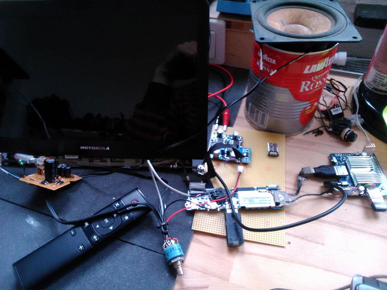
The end result looks like this, and yes, it still needs an enclosure:


Hey Not sue if you may read this, i noticed your pinouts of the Lapdock and was wondering if you may provide some assistance. BAsically im looking for alternate solder points for the USB line from the JHDMI connector. Wandering if you may have come accross this when working on this project?
LikeLike
Hi James.I'm not sure if you'd reach those, but my best bet is the USB line go to the chips below the shielding. If you find the pinout for those chips you'll find the USB connection…
LikeLike