UPDATE: I made the thing a project on GitHub. You can find information and can download the source code for the Arduino and PC programs from the project page.
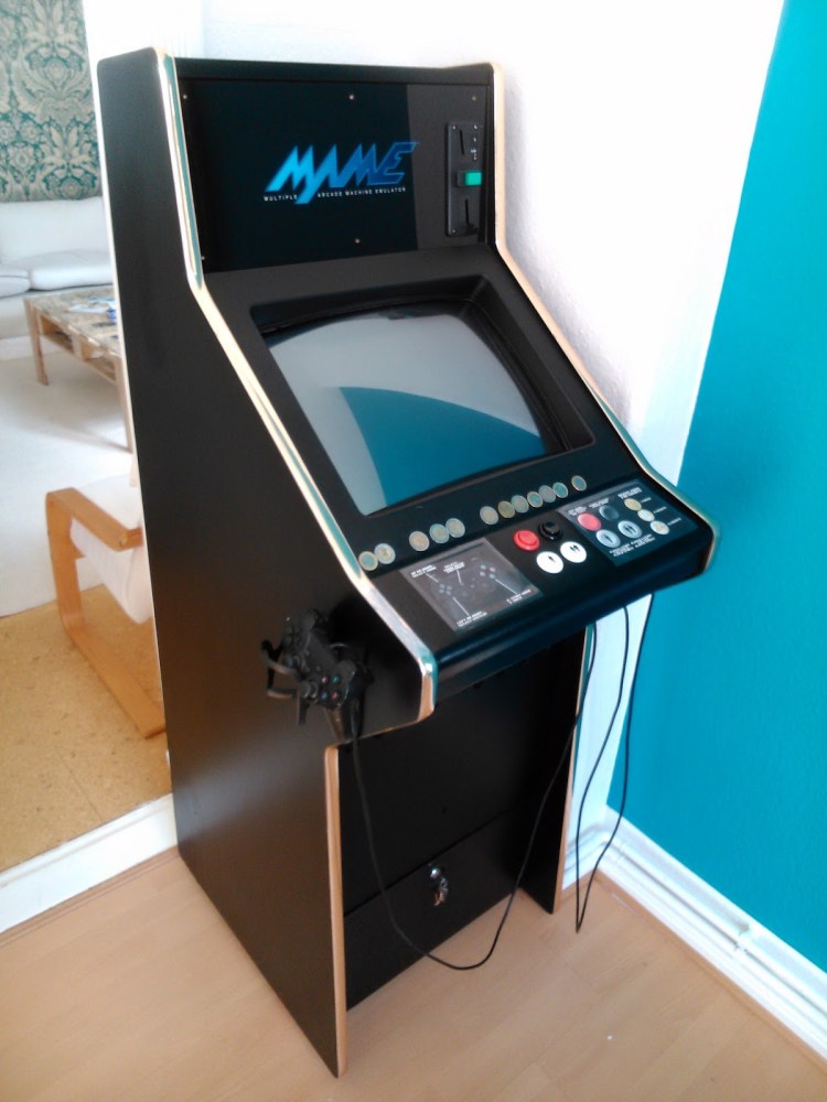
Ok. So I found this old arcade cabinet for 1,50€ 😀 on Ebay and managed to carry it up the stairs. Looks dandy and even has a €uro coin receptor, speakers and a nice marquee. Now what?!
I have PC hardware, a coin receptor, USB gamepads and some arcade buttons, but I need to connect them all to the mainboard. There’s multiple emulators I want to run (MAME, SNES, Gameboy / Color / Advance, …) and different games that may also need analog input, thus I went for USB gamepads (cheap PS2 copies). All emulators only accept joysticks and keyboard key presses, plus I also need to boot the PC and so on. There are commercial solutions like the iPAC, Xin-Mo XM-02 and others, but where’s the fun in that…
My setup is as follows:
- MSI H61M-P31 (G3) mainboard with Core i3 processor (power and reset button)
- MoneyControls SR3 Type2 coin receptor (3 coins, reject button and a switch to reject all coins)
- Arduino Leonardo
- 4 arcade push buttons (1 Player, 2 Players, Exit emulator, Pause emulation)
Electrics
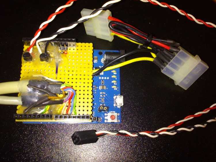
The Leonardo can send keypresses, detect inserted coins and power on the PC. To connect all wires and place some components I used a prototype board and some extra long Arduino pin headers to make a simple, crappy looking Arduino shield.
The Arcade buttons are connected to Arduino pins 2-4, with the pins set to INPUT_PULLUP, so a low level means they have been pressed. Simple.
The coin detector (datasheet mirror) is a bit harder to connect properly. First it needs 12-24V power, but only needs to work when the PC is on, so I just connected it to the 12V rail of a drive connector (lower left in fritzing sketch). The datasheet is long, but what’s important is this:
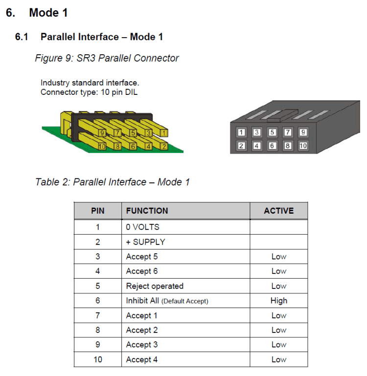
The coin receptor has open-collector outputs for the output pins so it can be directly connected to the Arduino. The outputs short a pin to ground for 50-100ms via a transistor when a coin is inserted or the reject button is pressed. So we can again set the Arduino pins 8-10 (coin 1-3) and 11 (reject button) to INPUT_PULLUP and a low level means that a coin has been inserted resp. the reject button has been pressed. Arduino pin 12 is set as an output and is connected to the “Inhibit All” pin. That pin makes the coin receptor reject all coins when it is set to high (the level must be > 2V) and this is the default we use.
To start the PC via the Arduino we need to have power. Some mainboards have a function to power USB devices when switched off, which you can toggle in the BIOS. Mine had that option, plus a jumper on the mainboard, but I didn’t manage to make the Arduino turn the PC on that way, so I needed a workaround…
The ATX standby power pin (pin 9 on ATX connector, purple wire) provides 5V even when the PC is off. I simply cut into the power connector from the ATX power supply and soldered a wire to +5Vsb and GND and placed a pin header on the shield (center, leftish).
Pins 6 and 7 connect to the reset (orange wire) and power (white wire) connectors of the main board which need to be shorted to activate the resp. function. I used 2N7000(A) N-Channel FETs for that which I had laying around. The 10k resistors are connected to ground and to the gate of the FET, so that when you connect the power supply and the Arduino hasn’t started up yet, the gate is pulled low, and the FET doesn’t switch on. After the Arduino has started up it can then pull pin 6 or 7 high to either power on/off or reset the PC.
Pin 13 (brown wire, upper left) is used as a hardware fail-safe for the keyboard functionality in the final program. When it is high (connected to 5V) the Arduino doesn’t send actual keyboard commands, but redirects them to the serial port. So when you’ve screwed up you won’t get bombarded with bogus keypresses.
The final Fritzing layout can be seen here (and downloaded here):
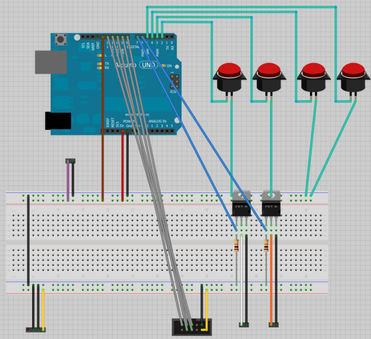
There was a slight problem though. The Arduino was connected to +5Vsb via the 5V pin AND the USB port. The power from the Arduino via USB somehow confused the mainboard and it didn’t power on properly. I finally figured out that I had to remove the polyfuse (lower right corner next to the reset button in the photo above, marked “501k”) from the Arduino board to make it work. I replaced it by a pin header and soldered the fuse to some pins so I can re-connect it when needed.
Test software
A simple test program for the Arduino can be downloaded here. It sends “A”, “B”, “C”, “D” via the serial port when a button is pressed. Button A also powers on the PC, button B resets it. When a coin is inserted it sends “1”, “2”, “3” for coin 1-3. The reject button sadly didn’t work on my receptor…
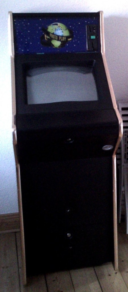
This is the finished thing btw. It uses Ubuntu, Emulationstation and libretro, boots up in seconds and even features bottle-holders on both sides! 😉