This thing started long ago when I got the laptop. I love it, but it really lacks a backlit keyboard. There was one excellent thread with people presenting solutions (add tiny switches, soldering to the bluetooth connector, to the USB breakout board etc.), but I found none of them really satisfying. I decided to void my warranty, build a circuit and connect it to the useless „P“-Button already available. After all: „If you can’t open it, you don’t own it!“ – MAKE: Magazine 😉

A friendly warning: This will void your warranty – all the way. You’ll have to completely take apart your laptop, solder tiny SMD components to PCBs and hair-thin cables to your mainboard, cut traces and apply hot glue everywhere. Continue only if you know what you’re doing! I take no responsibility whatsoever. There be dragons…
What you’ll get:
- A backlit keyboard
- Brightness controlled by the „P“-button in 5 steps (from off->brighter…-> to off)
- Backlight turns off when LCD backlight goes off
- Last setting is restored when backlight goes on again
What you’ll need:
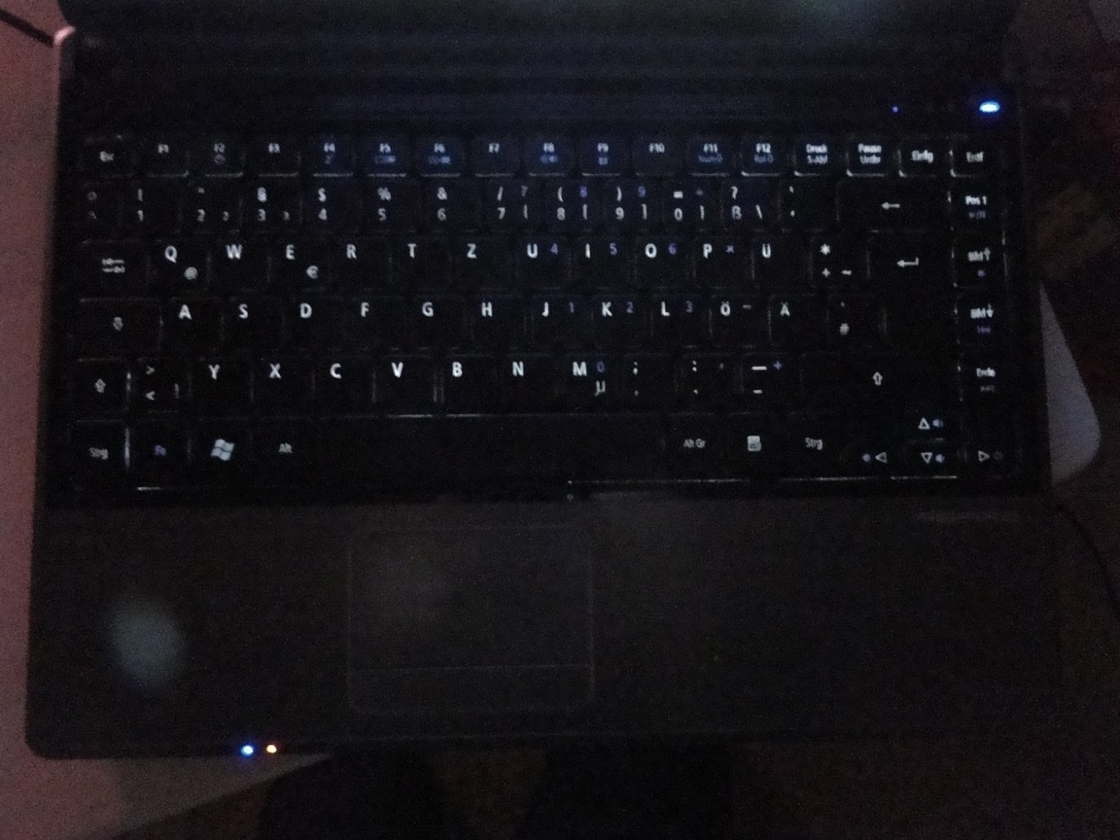
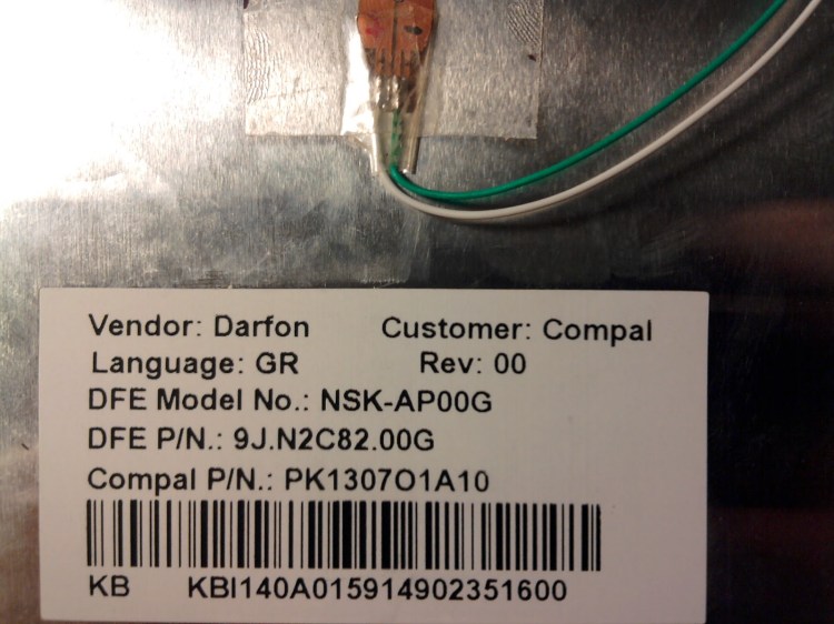
- The actual backlit keyboard (search for keyboards for the Acer Aspire 3810 model)
- A custom PCB (EAGLE files available)
- SMD components (PIC 10F202T, N-channel FET BSS138 or 2N7002, 3x10k resistors 1206 types)
- A PIC programmer (code + binary available)
- Really thin wires
- Low-watt soldering iron with a tiny tip and SMD soldering experience
- „Carpet“/exacto knife
- Hot glue gun
The keyboard I got from Ebay was ~30€. You can see the backlight LED supply cables already attached. The backlight is not very bright, but totally sufficient for me.
1. Build the circuit board
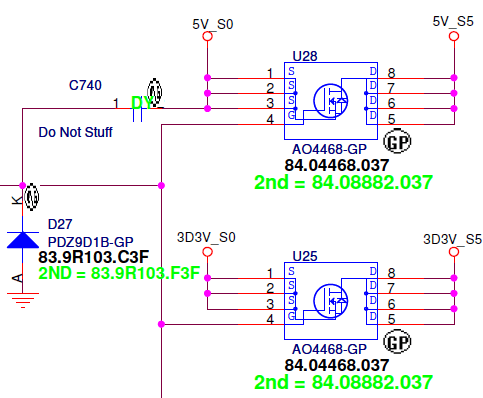
First step is to build the circuit board. It is controlled by a PIC10F202T, a tiny 6-pin MCU running at 4MHz. This is the schematic:
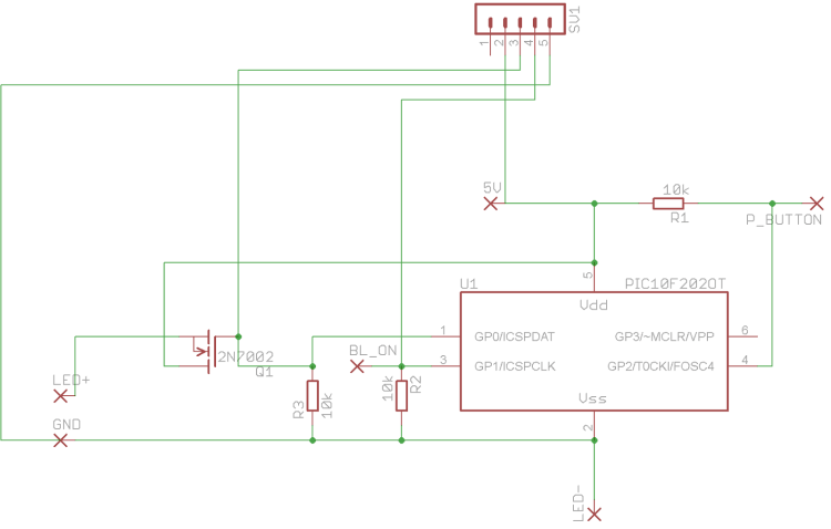
The PIC controls a FET that is able to switch the current needed for the backlight LEDs. The brightness is controlled by PWM . The FET should have a low RON-resistance. I used a BSS138, but a 2N7002 might actually be a better choice. The PIC input pins are connected to the „P“-Button (P_BUTTON) for switching through backlight brightness levels (switches to GND) and to the LCD display „backlight on“ pin (BL_ON). That one provides 3,3V while the LCD backlight is on.
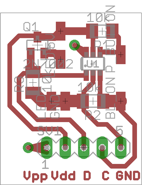
You can see the PCB for the schematics at the right side. I provided solder pads for connecting a PIC programmer (Vpp, D, C, …). You can cut that part off after you’ve tested and are satisfied with the operation of the circuit and then install the thing into the laptop. You have to remove the excess parts of the circuit board to make it fit one of the openings below the keyboard.
You’ll need to use a PIC programmer to write code onto the PIC. I used USBPICPROG, a cheap (~25€), open source programmer, with free software. There is a „3820_BL.production.hex“ file containing the binary under „/dist/default/production/“ in the ZIP. There’s also source code provided in case you’d want to change functionality. You can compile it with the excellent, free PIC development system MPLAB X from Microchip (http://www.microchip.com/mplabx/).
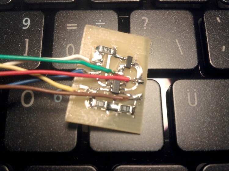
This is more or less what it looks like when it is assembled and has wires connected (older revision btw.). You can see that it’s pretty small…
2. Disassemble the laptop
After you’ve assembled, programmed and tested the circuit board you’ve got to solder wires to some points on the laptop mainboard.
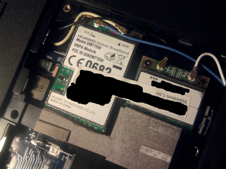
First disassemble the laptop. Remove the keyboard using a screwdriver to carefully push the plastic pieces securing the keyboard in place back so you can lift the keyboard. There are 5 of them at the top part of the keyboard. Be careful with the ribbon cable below! Then remove all screws located below the keyboard, flip the laptop around and remove all screws at the bottom too. There are plenty. After opening the „hatch“ at the bottom remove the harddisk (left), the RAM (center), and carefully remove the WiFi and 3G card (right part). Be sure to take a photo of which antenna cable goes where (blue, yellow, black, white). Here’s what mine looks like:
Use a thin piece of plastic to remove the front and back part of the case. When removing the front part of the case be careful to first detach all ribbon cables.
3. Modify the P-Button breakout board
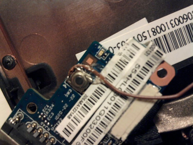
The front part of the case has the breakout board with the RJ45 LAN-connector attached to it at the left side. Remove the screw, take it out, turn it around and peel the labels off. Notice switch SW3. That’s the „P“-button. When pressed it connects the line to GND, but we want it to change its functionality, so you’ve got to cut the trace connecting it to the mainboard. That trace leads from the SW3 to the little solder spot just below the label „R11“ and then on to the connector that goes to the mainboard. That’s where you want to cut it using a sharp „carpet“/exacto knife (see picture).
Solder a really thin wire to the top left connector of SW3 (see picture) and fix the wire to the board with some hot glue. After that you may put the breakout board back in place.

4. Power supply
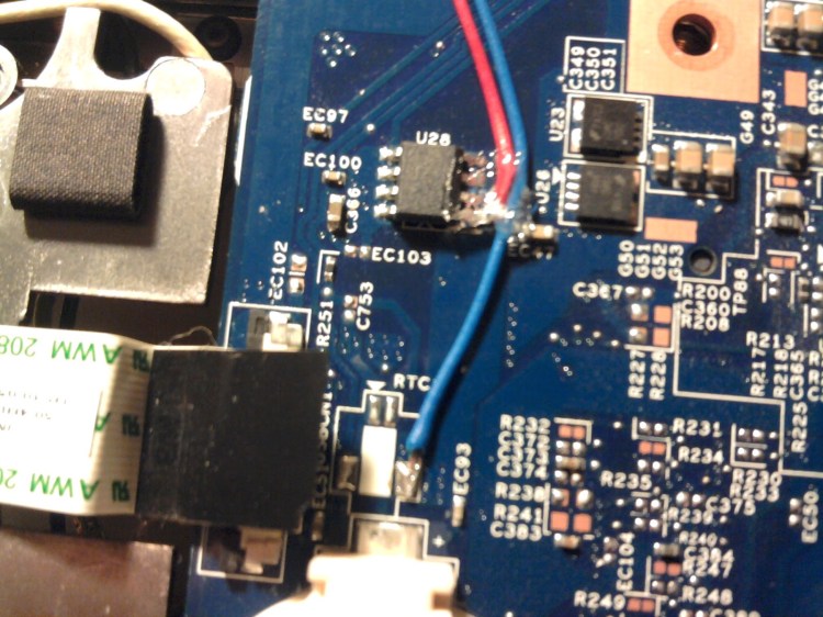
We need a supply voltage for the whole thing which we can find at the pins of U28, located on the front of the mainboard at the lower left. That chip is a switch to toggle the USB ports at the left side of the laptop on and off.
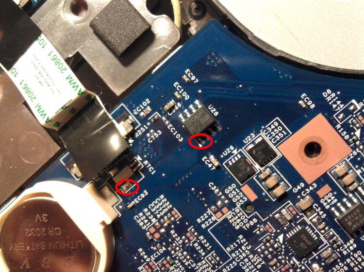
We want permanent power when the laptop is on, so we connect the 5V pin of our circuit to pin 1 of U28 (pin 1, see picture). GND can be connected to the big solder pad between „RTC“ and „EC93“ (see picture) or anywhere else you find GND. Solder the wires and again fix them with some hot glue.
5. The BL_ON pin
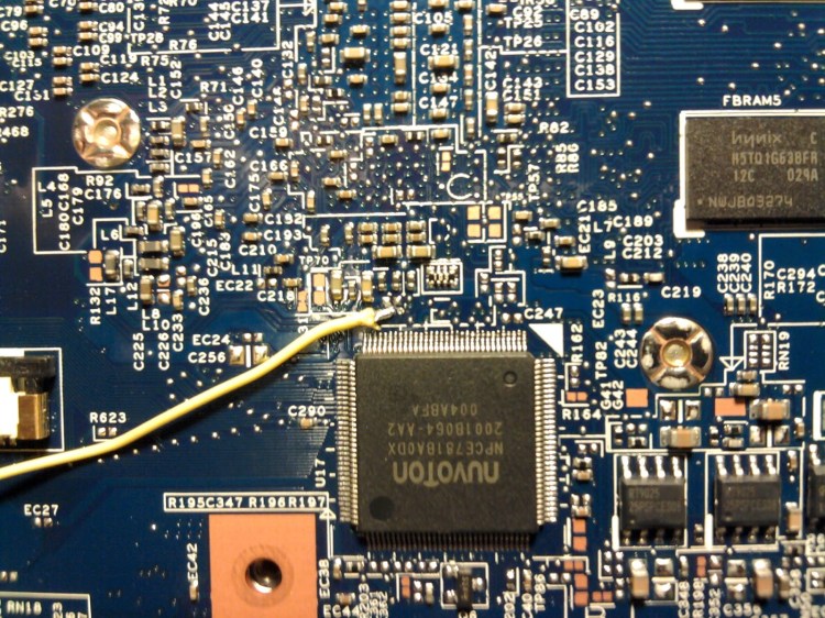
Now it becomes a bit tricky. Take a look at the front side of mainboard and locate U17, the LPC controller (square, 128 pins, located at lower center). This chip controls the LCD backlight through pin 27 (BLON_OUT) which is connected to pin 5 of the LCD connector.

But both places are not solderable without bridging pins. Just above pin 27 is a via (connection to another layer of the mainboard). It is the left one of two vias close to each other (one over pin 25, one over pin 27, see picture). Use a „carpet“/exacto knife to CAREFULLY scratch off the lacquer until you see a copper „ring“. Dont scratch off too much, otherwise you might break the via and your LCD backlight will be gone… Once you’ve got a solderable spot, solder a wire that will be connected to BL_ON on our circuit board. Again, fix it with some hot glue, best directly where you’ve soldered it to the mainboard.
6. Putting it back together
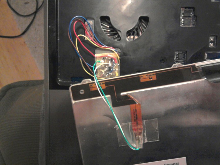
That was the hard part. Now re-assemble the laptop again while making sure all wires end up coming out of the lower left opening in the front case below the keyboard (see picture below). There is space for the circuit board too.
7. Install the keyboard
You might need to prepare your keyboard so it fits in place of the old one. It will probably be a bit too thick, so there’s two things you need to do. First bend down the „noses“ at the lower part of the key board ~10° using some universal pliers or whatever. Bend them until the keyboard fits nicely…
Then you’ll have to file down (or use a „carpet“/exacto knife) the 7 „dents“ at the left, right and at the top of the keyboard by a good amount (~1-2mm) so the plastic securing pins can snap in place. Again you’ll have to try what works in your case…
After the keyboard fits solder all the wires from the mainboard to the circuit board. Also solder the wires from the keyboard backlight to the circuit board. Try if the keyboard backlight control works. You don’t have to boot up. Just enter the BIOS or something. Try pressing „Fn“+“F6“ to turn the LCD backlight off.
When all’s fine wrap the circuit board in some tape and place it in the lower left opening below the keyboard, then put the keyboard back in place.
Hooray! You’re done. Enjoy your keyboard backlight.
References:
Here are some docs for the Acer 3820T(G), which is based on the JM31-CP mainboard, that you might find useful:
Processor upgrade directions
JM31-CP schematics
Acer Aspire 3820T(G) service guide

You're dead on. If you can't open it, you don't own it. If you don't own it, it's no fun hacking away your gadgets. Do you have a video of your laptop with the backlit keyboard?p.s. Thanks for the informative share. I'm surprised no one has followed up on this hack.
LikeLike
Thanks for your comment.Sorry though, no video. But take my word that the backlight is totally sufficient for working in the dark 🙂
LikeLike
Wow, you did a great job! I would like to make your design for my laptop, but paying setup costs to order just 1 or 2 pcbś is not nice. Maybe do you have a spare pcb lying around that I could buy? Or can you refer me to a company that can make small amounts cheaply?
LikeLike